|
Location:
|
Raft River, Idaho
|
Accident Number:
|
WPR24LA265
|
|
Date & Time:
|
August 2, 2024, 21:07 Local
|
Registration:
|
N20BH
|
|
Aircraft:
|
Bell 407
|
Aircraft Damage:
|
Substantial
|
|
Defining Event:
|
Electrical system malf/failure
|
Injuries:
|
4 Minor
|
|
Flight Conducted Under:
|
Public aircraft
|
|
|
Analysis
The pilot of the helicopter departed on the final stage of a multi-leg public use contract flight to reposition a helitack crew. The U.S. Forest Service (USFS) contract specified that operations were restricted to day visual meteorological conditions; the planned arrival time at the destination was about 30 minutes after sunset and just short of the 14-hour limit of the pilot’s duty day.
Review of onboard video recordings revealed that, about 18 minutes after takeoff while in level flight, the measured gas temperature (MGT) exceeded the limits allowed for cruise flight. The overtemperature indication triggered a “CHECK INSTR” annunciation and an exceedance recorded by the MGT gauge, which could only be reset by a mechanic after the flight. Following this, the pilot then appeared to reduce engine power and continued the flight.
About 30 minutes later, the barrier inlet filter caution light illuminated. The pilot found this indication unusual, because the filter had been serviced the week prior. He activated the filter bypass system and continued with the flight. Due to arrival time constraints, the crew discussed the option of diverting to an alternate airport and staying there overnight; however, they ultimately decided to continue to the destination.
Shortly thereafter, the MGT gauge began to indicate a temperature increase into the yellow range and then the red range, accompanied by another “CHECK INSTR” warning. The pilot perceived this indication, and the helicopter’s response as he began to troubleshoot, as evidence of an engine overspeed condition, and he chose to initiate a precautionary landing to an open field nearby. Review of the cockpit video, however, revealed that none of the other engine gauges corroborated the high MGT reading, consistent with an erroneous MGT indication. When his control inputs failed to arrest the perceived overspeed or restore normal engine response, the pilot entered an autorotation to a closer cornfield.
The autorotation was conducted during the diminishing ambient light conditions of dusk. The lighting conditions, combined with the height of the corn, obscured the pilot’s depth perception and limited his ability to accurately judge the timing of the landing flare, resulting in a hard landing. Impact forces were sufficient to cause separation of the main transmission, fragmentation of drive system components, and extensive secondary damage to the engine, including fragmentation of the turbine wheels after hard-body ingestion.
Postaccident examination revealed no evidence of pre-impact mechanical failure, fatigue, or thermal distress of the engine, and review of the engine control unit’s (ECU) non-volatile memory did not reveal any event indicative of an engine overspeed, overtemperature, or associated malfunction. Bench testing of the MGT gauge did not reveal any anomalies, and despite the in-flight display irregularities, the gauge recorded only one exceedance, which appeared to match the initial overtemperature indication observed earlier in the flight.
However, the erroneous displays observed during the flight could be simulated during bench testing by lowering and then restoring the unit’s electrical supply voltage. Therefore, the condition was likely caused by an undetermined disruption in the electrical supply to the MGT gauge.
The accident sequence was initiated by compounding operational stressors. The accident occurred at the end of a long duty day for the pilot, who likely was beginning to feel the effects of fatigue, and the flight was conducted at a time of day that would have created significant time pressure. The pilot then allowed the engine to operate above normal MGT levels, possibly to expedite arrival. Although power was reduced and the flight continued, the overtemperature indication further increased the pilot’s cognitive workload, and the need for a mechanic to intervene later would have been an additional stressor.
The unexpected barrier inlet filter annunciation that followed likely increased the pilot’s anxiety, and although a diversion was discussed, the prospect of an overnight stop and the resulting logistical impacts contributed to plan continuation bias. Subsequent anomalous MGT indications became the triggering event that overwhelmed the pilot, who misdiagnosed the symptoms as a developing engine problem that he likely attributed to the earlier issues.
Probable Cause and Findings
The National Transportation Safety Board determines the probable cause(s) of this accident to be:
The pilot’s misdiagnosis of an erroneous engine instrument indication and his subsequent decision to enter an autorotation, which resulted in a hard landing due to degraded visual cues and low ambient light conditions. Contributing to the accident were the erroneous engine indications likely caused by an undetermined electrical supply disruption; time pressure, pilot
fatigue, and plan continuation bias as daylight diminished and the crew aimed to complete the flight; and cognitive overload from multiple airframe and engine caution indications.
Findings
Factual Information
History of Flight
On August 2, 2024, about 2107 mountain daylight time, a Bell 407 helicopter, N20BH, was substantially damaged when it was involved in an accident near Raft River, Idaho. The pilot and three passengers sustained minor injuries. The helicopter was operated as a public aircraft in support of the USFS.
The helicopter was privately owned, and the flight originated under the Bureau of Land Management’s use of a USFS Exclusive Use flight service contract.
The purpose of the flight was to transport three USFS helitack crew members from Gerlach, Nevada, to their base at Pocatello, Idaho, with intermediate stops at Winnemucca and Elko, Nevada. The pilot reported that the first two legs were uneventful, and that the accident occurred on the final leg.
On the day of the accident, sunset at Pocatello was 2049. The terms of the contract limited operations to day VFR only. The crew planned to arrive at 2120; however, according to the pilot, they were given permission to arrive as late as 2125, which was possible as long as he maintained a groundspeed of 120 knots while enroute.
The pilot stated that, about 55 minutes after departing Elko, the barrier inlet air filter light started to flicker. The filter had been serviced the week prior, and although the helicopter had been flying in a dusty and smoky environment since then, he thought such an activation was premature. A short time later, the filter light transitioned from flickering to on, and the pilot activated the filter bypass system by pressing the “FILTER” light switch. Due to arrival time restraints, the crew then discussed the option of diverting and completing the flight the following morning but chose to continue to Pocatello.
The pilot reported that, a few minutes later, he noticed the engine MGT starting to rise into the yellow band of the gauge. In response, he reduced power and began to descend. However, the MGT continued to rise, and at an altitude between 1,000 and 1,500 ft, it continued to climb past the gauge redline. The pilot decided to make a precautionary power-on landing and began
looking for a suitable landing area. As he was maneuvering the helicopter toward a grass field, he determined that the engine was starting to overspeed.
The pilot raised the collective control twice to try to arrest the overspeed, but the engine did not respond, so he decided to perform an autorotation into an adjacent corn field. Due to the corn's unknown height, the pilot was unable to determine the optimal time to initiate the flare, and the helicopter landed hard after dropping from about 5 ft above the ground. The pilot reported that immediately after landing, the engine came back on for about 10 seconds and was shaking the aircraft and crew violently.
Pilot Information
|
Certificate:
|
Commercial
|
Age:
|
54,Male
|
|
Airplane Rating(s):
|
None
|
Seat Occupied:
|
Right
|
|
Other Aircraft Rating(s):
|
Helicopter
|
Restraint Used:
|
4-point
|
|
Instrument Rating(s):
|
Helicopter
|
Second Pilot Present:
|
|
|
Instructor Rating(s):
|
Helicopter
|
Toxicology Performed:
|
|
|
Medical Certification:
|
Class 2 Without waivers/limitations
|
Last FAA Medical Exam:
|
January 9, 2024
|
|
Occupational Pilot:
|
Yes
|
Last Flight Review or Equivalent:
|
May 31, 2024
|
|
Flight Time:
|
3855 hours (Total, all aircraft), 908 hours (Total, this make and model), 3572 hours (Pilot In Command, all aircraft), 69 hours (Last 90 days, all aircraft), 7 hours (Last 24 hours, all aircraft)
|
The pilot reported 3,855 total hours of flight experience, including 69 hours in the 90 days preceding the accident, and 26.8 hours of flight time during the previous 7 days. He had accumulated 908 hours in the Bell 407 and was issued an interagency pilot qualification card by the USFS on June 10, 2024
On the day of the accident, the pilot was dispatched from the Pacific time zone, where his duty day began at 0700. Crew duty days are limited to 14 hours; a 14-hour duty day starting at 0700 PDT would have concluded by 2200 MDT.
Aircraft and Owner/Operator Information
|
Aircraft Make:
|
Bell
|
Registration:
|
N20BH
|
|
Model/Series:
|
407
|
Aircraft Category:
|
Helicopter
|
|
Year of Manufacture:
|
1998
|
Amateur Built:
|
|
|
Airworthiness Certificate:
|
Normal
|
Serial Number:
|
53242
|
|
Landing Gear Type:
|
None; Skid
|
Seats:
|
7
|
|
Date/Type of Last Inspection:
|
January 5, 2024 Annual
|
Certified Max Gross Wt.:
|
6000 lbs
|
|
Time Since Last Inspection:
|
127.2 Hrs
|
Engines:
|
1 Turbo shaft
|
|
Airframe Total Time:
|
10475 Hrs at time of accident
|
Engine Manufacturer:
|
ALLISON
|
|
ELT:
|
C126 installed, activated, did not aid in locating accident
|
Engine Model/Series:
|
250-C47
|
|
Registered Owner:
|
CHEMAIR HELICOPTERS INC
|
Rated Power:
|
600 Horsepower
|
|
Operator:
|
Brainerd Helicopter Services
|
Operating Certificate(s) Held:
|
Rotorcraft external load (133), On-demand air taxi (135), Agricultural aircraft
(137)
|
|
Operator Does Business As:
|
|
Operator Designator Code:
|
BRNA
|
Meteorological Information and Flight Plan
|
Conditions at Accident Site:
|
Visual (VMC)
|
Condition of Light:
|
Dusk
|
|
Observation Facility, Elevation:
|
KBYI,4157 ft msl
|
Distance from Accident Site:
|
24 Nautical Miles
|
|
Observation Time:
|
20:53 Local
|
Direction from Accident Site:
|
272°
|
|
Lowest Cloud Condition:
|
Clear
|
Visibility
|
10 miles
|
|
Lowest Ceiling:
|
None
|
Visibility (RVR):
|
|
|
Wind Speed/Gusts:
|
/ Turbulence Type
Forecast/Actual:
|
/
|
|
Wind Direction:
|
Turbulence Severity Forecast/Actual:
|
/
|
|
Altimeter Setting:
|
30.11 inches Hg
|
Temperature/Dew Point:
|
27°C / 13°C
|
|
Precipitation and Obscuration:
|
No Obscuration; No Precipitation
|
|
|
Departure Point:
|
Elko, NV (EKO)
|
Type of Flight Plan Filed:
|
Company VFR
|
|
Destination:
|
Pocatello, ID (PIH)
|
Type of Clearance:
|
None
|
|
Departure Time:
|
18:40 Local
|
Type of Airspace:
|
Class G
|
Airport Information
|
Airport:
|
NONE
|
Runway Surface Type:
|
|
|
Airport Elevation:
|
|
Runway Surface Condition:
|
Dry;Vegetation
|
|
Runway Used:
|
|
IFR Approach:
|
None
|
|
Runway Length/Width:
|
|
VFR Approach/Landing:
|
Forced landing
|
Wreckage and Impact Information
|
Crew Injuries:
|
1 Minor
|
Aircraft Damage:
|
Substantial
|
|
Passenger Injuries:
|
3 Minor
|
Aircraft Fire:
|
None
|
|
Ground Injuries:
|
|
Aircraft Explosion:
|
None
|
|
Total Injuries:
|
4 Minor
|
Latitude, Longitude:
|
42.531213,-113.23015
|
The helicopter came to rest in a cornfield about 41 miles southwest of Pocatello. At the accident site, the surrounding corn stalks were about 6 ft tall. The helicopter was in a level attitude, with the main skids splayed outward such that the cabin belly was resting on the ground.
The main rotor transmission assembly detached from the airframe and had rotated left and dropped down into the cabin compartment. The engine, which sat behind the main transmission, remained attached to the airframe. The engine output drive shaft and associated couplings had failed forward of the engine, resulting in fragments of the surrounding structure and drive components being propelled up into the inlet plenum.
Three of the four main rotor blades remained attached at the hub, and the fourth was partially attached and bent opposite the direction of rotation. Two blades were shattered about midspan, with their remaining fragments located within the immediate vicinity of the accident site.
The tail rotor and associated gearbox had detached and were located about 30 ft from the main wreckage.
Flight recorders
The helicopter was equipped with an Appareo Vision 1000 cockpit image recording device mounted to the cabin roof. The unit contained an internal camera and a GPS receiver that captured time, position, altitude, and speed. The unit also had a self-contained real-time inertial measuring unit capable of recording 3-axis acceleration and derived pitch, roll, and yaw data.
The unit was sent to the NTSB Vehicle Recorders Division for data extraction and a video group reviewed the data. Review of the video showed that the pilot was seated in the right seat, with a crew member in the left seat. The recording began about 7 minutes before takeoff after an uneventful engine start. The helicopter departed at 1947:41. Engine gauge indications for the next 10 minutes as the helicopter flew northeast were within the normal operating parameters, with MGT remaining just below the 727° C maximum continuous operating range.
At 2005:47, the MGT gauge began to show an increase in temperature into the takeoff range and the display began to flash, accompanied a short time later by a brief illumination of the “CHECK INSTR” light on the annunciator panel. MGT then briefly dropped back to 727° C, after which it began to climb. About 30 seconds later it had reached 736° C. The CHECK INSTR light then came back on and remained illuminated for the rest of the flight. The pilot then pointed to the MGT gauge, as it dropped down to 710° C.
The flight proceeded while making heading and altitude changes to avoid terrain, and after 30 minutes, the barrier filter alert could be seen reflected in the passenger’s helmet. The pilot reached for the overhead panel, and at 2102:29, he turned on the instrument panel lights as the sky grew darker.
At 2106:16, the MGT radial and numeric indicator began to display missing and random segments, and the temperature began to climb. (see figure 1.) The HYD SYSTEM light briefly illuminated for 1 second, and there was no corresponding change in the other engine parameters. About 20 seconds later, MGT had reached 840° C, and the vertical speed indicator was showing a 1,200 ft per minute (fpm) descent rate. The airspeed slowed to 115 kts, torque dropped to 43.6%, and gas generator speed (NG) dropped to 91.7%, while power turbine speed (NP) and main rotor speed (NR) remained constant at 100%.
The MGT gauge then appeared to perform a built-in-test, or BIT check, where all segments of the display illuminated. (see figure 1.) By the time the unit had come back online, it was showing a temperature of just below 500° C on both the segmented display and radial indicator.
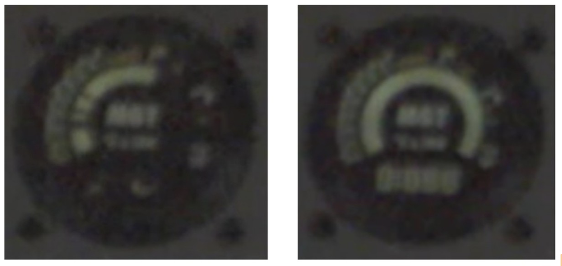
Figure 1 – MGT rising with missing segments (left). BIT check (right)
By this time, the helicopter had descended to 5,000 ft mean sea level (780 ft above ground level [agl]) and was descending at a rate of 750 fpm, at an airspeed of 97 kts. The torque gauge indicated 6.4%, and both NP and NR were still at 100%.
About 5 seconds later, at 2105:53 with NP remaining at 100%, NR increased to 103% and both the ambient noise pitch and volume increased consistent with increasing rotor rpm, followed by the illumination of the rpm light. At this time, NR was 107% and NP was 100%, with MGT indicating 475° C.
By the time the helicopter had descended to about 120 ft agl, the rotor rpm light illuminated accompanied by the aural low rotor rpm tone. NR was at 94% as the helicopter began to pitch up in a manner consistent with it beginning a flare, and a few seconds later the helicopter violently impacted the ground.
Tests and Research
MGT Indicator Gauge
The helicopter’s MGT gauge screen was composed of a segmented radial temperature indicator with color-coded bands, along with a series of seven-segment displays that indicated the temperature numerically along with the exceedance status. (see figure 2.) On power-up or
under conditions where the unit sensed a software or hardware anomaly, it was designed to perform a BIT, which included an illumination of all display segments.
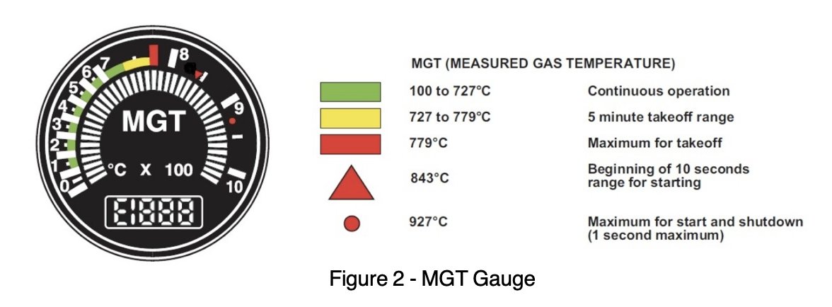
Figure 2 - MGT Gauge
The gauge, in correspondence with the flight manual’s engine operating guidance, indicated a continuous operating temperature of 100 to 727° C with a green band.
The 5-minute takeoff range temperature was between 727° and 779° C and denoted by a yellow band. The maximum takeoff temperature was 779° C and indicated by a red bar.
The transient, 12-second range was between 780° and 843° C with the upper limit bound with a red triangle, and the maximum start and shutdown range, which was not to exceed 10 seconds above 843° C or 1 second at 927° C, was indicated by a red circle.
The design of the unit was such that if the temperature was in the yellow takeoff region (727° to 779° C) for 4 ½ minutes the segments of the display would flash as a warning. If this temperature condition continued for an additional 30 seconds, the numeric display would show an “E” indicating that an exceedance had been logged in non-volatile memory (NVM). An amber CHECK INSTR caution light would also illuminate on the annunciator panel if an MGT exceedance was about to or had occurred. An exceedance would also be logged into if the temperature climbed into the transient range (780° to 843° C) for more than 10 seconds, or if it ever entered the transient upper limit.
Once the exceedance flag was triggered, the “E” indication remained on the screen until a mechanic reset it using specialized software.
MGT Indicator Gauge Examination
The unit was examined and tested at an FAA-certified overhaul facility, in accordance with an approved test protocol, and no anomalies were noted. It was found that by lowering the input supply voltage to around 6 volts direct current (VDC), the unit would exhibit the increasing MGT behavior observed during the accident sequence. Once it had dropped below 6VDC, the unit
would display random characters in a manner almost identical to that observed before the accident. With the restoration of supply power to the nominal 28VDC, the unit restarted and performed a BIT check, consistent with that observed during the accident flight. (see figure 3)
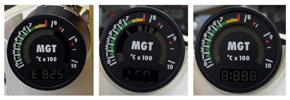
Figure 3 – Increasing MGT (left), increasing with random segments (center), BIT check (right).
The unit’s memory was accessed using the standard maintenance software, and one exceedance had been recorded (the unit can record 50 exceedances).
This exceedance was for 737° C and lasted 5 seconds. It was recorded on the day of the accident and appeared to be consistent with when the CHECK INSTR light came on and stayed on after the overtemperature indication during the initial cruise phase of the flight.
MGT Gauge Airframe Installation
The MGT indication system comprised the indicator mounted to the center instrument panel, which was supplied with electrical power via a 3-amp circuit breaker mounted to the overhead panel. The MGT signal was captured by 3 thermocouples connected in parallel and mounted to the engine exhaust section. The thermocouples provided data to both the MGT instrument and the ECU.
On the airframe, the MGT circuit breaker was found in the closed (pressed) position. The circuit breaker performed appropriately when tested, and the entire electrical supply and ground wiring for the MGT system were examined and tested. No short or open circuits were observed, all cannon plugs and connector fittings were intact and free of corrosion, and there was no evidence of electrical arcing, thermal damage, or exposed conductors through cable chafing.
Engine Examination
Examination of the Rolls-Royce M250-C47B engine revealed evidence of hard body ingestion and engine uncontainment. All impeller inducer blades exhibited impact damage, tears/rips, missing material, and distortion, while the exducer blades exhibited shiny contact wear
consistent with contact with the compressor shroud housing. The engine exhaust duct, exhaust collector support, horizontal firewall shield assembly, and right compressor discharge tube exhibited varying degrees of pockmarks and exit holes. Looking through the exit hole in the exhaust collector support, the stage 4 turbine wheel was observed, with all blades fractured transversely at their roots.
The engine was examined and disassembled at the facilities of Rolls-Royce under the supervision of engineers from the NTSB.
Examination revealed continuity between the compressor and accessory gearbox, but not with the gas producer turbine.
The tie bolt, which secures the gas producer stages 1 and 2 wheels together, was found fractured, as was the turbine-to-compressor coupling shaft that connects the gas producer turbine to the accessory gearbox. The No. 6 roller bearing inner race and power turbine coupling shaft, which connects to the power turbine-to-pinion gear shaft, was also fractured. The turbine shaft-to-pinion gear coupling was fractured and no longer coupled to the inside spur teeth of the helical gear, but remained seized within the helical gear bore. All the blades on stages 1, 2, and 3 turbine wheels were present and fractured transversely across the airfoil; the stage 4 turbine wheel blades were fractured at the platform. Both the gas producer and power turbine exhibited extensive rotational damage throughout, consistent with stationary and rotating parts/components circumferentially and longitudinally contacting one another.
The gas producer turbine and power turbine components were submitted for material analysis. No parts were found with any pre-existing anomalies or fatigue fractures; all damage appeared consistent with secondary damage following loss of axial and radial control of the components during the ground impact sequence.
Engine Control Unit
The engine was equipped with a dual-channel ECU, manufactured by Triumph Engine Control Systems.
The ECU included an incident recording feature, which was intended to provide data in support of engine troubleshooting and maintenance. The system was designed to activate after a successful engine start, then continuously record data every 1.2 seconds over a 12-second loop, resulting in a stream of the last 10 sets of data. When an incident was detected, the 10 sets of data recorded pre-incident were saved, directly followed by an additional 40 sets of post-incident data. Each data set included critical parameters such as engine history, discrete words, fault words, and key control inputs.
The unit sustained impact damage during the accident sequence; however, the integrity of its recording components was established. The data extract revealed no events that would have
met the threshold to trigger the incident recorder. Four undated limit peak events were recorded, none of which appeared to be related to the accident flight.
Administrative Information
|
Investigator In Charge (IIC):
|
Simpson, Eliott
|
|
Additional Participating Persons:
|
Jeremy Blanford; FAA Flight Standards District Office; Boise, ID Jack Johnson; Rolls Royce; Indianapolis, IN
Jeff McDermott; Brainerd Helicopters John Mills; U.S. Department of the Interior
Matthew Shaddle; Bureau of Land Management Matthew McLuckie; Bell Textron
Helen Tsai; Transportation Safety Board of Canada
|
|
Original Publish Date:
|
June 10, 2026
|
|
Last Revision Date:
|
|
Investigation Class:
|
Class 3
|
|
Note:
|
The NTSB did not travel to the scene of this accident.
|
|
Investigation Docket:
|
https://data.ntsb.gov/Docket?ProjectID=194840
|
READ MORE ROTOR PRO: https://justhelicopters.com/Magazine
WATCH ROTOR PRO YOUTUBE CHANNEL: https://buff.ly/3Md0T3y
You can also find us on
Instagram - https://www.instagram.com/rotorpro1
Facebook - https://www.facebook.com/rotorpro1
Twitter - https://twitter.com/justhelicopters
LinkedIn - https://www.linkedin.com/company/rotorpro